1. The polarization of the antenna is defined as the polarization of its radiated wave.
2. The polarization of EM wave is the direction of its electric field.
3. An electric field consists of both Eθ and Eϕ components.
4. The direction of rotation of electric field along the direction of propagation represents the sense of polarization.
- If the rotation is clockwise ➡ right-hand polarization.
- If the rotation is anti-clockwise ➡ left-hand polarization.
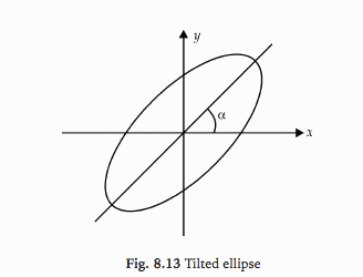
5. Generally, the polarization of antenna depends on the axial ratio (AR), the tilt angle (α) and sense of rotation (clockwise or anticlockwise).
6. Tilt angle determines the orientation of the ellipse as it is measured clockwise from the reference direction.
METHODS OF MEASUREMENT OF POLARIZATION:
1. Polarization pattern method.
2. Linear component method.
3. Circular component method.
4. Power measurement method.
(AUT (Antenna Under Test) is used in transmitting mode for measurement of polarization.)
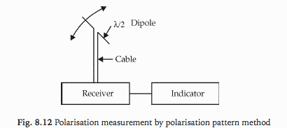
1. Polarization Pattern Method:
(a) In this, a rotatable half-wave dipole is connected to a calibrated receiver.
(b) The dipole is rotated and incident field coming from AUT (Antenna Under Test) is measured.
(c) Typical polarization pattern for different polarization of the test antenna is shown below.
(d) The sense of polarization is obtained by using two antennas. Here one is right-hand circular polarised and the other left-hand circular polarised. The antenna which receives a large signal gives the sense of polarization.
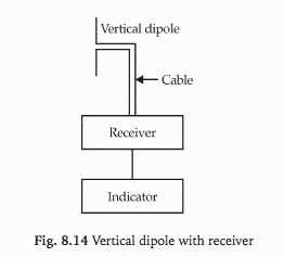
2. Linear Component Method:
(a) In this, the signal coming from AUT is measured by a vertical antenna. Let the signal be Ev.
(b) The vertical dipole is connected in the horizontal position and the signal is measured. Let the signal be Eh.
Ex = Ev sin (ωt − βz)
Ey = Eh sin (ωt − βz + α)
where,
α = phase difference between the two signals
(c) Phase difference α is measured by a phase comparative method in which signal from the horizontal antenna is connected to a matched terminated slotted line.
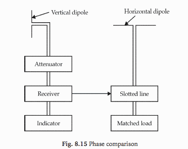
- If α lies in 0 < α < 180°, the direction of rotation is clockwise.
- If α lies in 0 < α < − 180°, the direction of rotation is anti-clockwise.
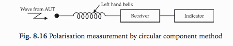
3. Circular Component Method:
In this method, two circularly polarized antennas of opposite sense, e.g. left and right-hand helical antennas are used to receive the signals EL and ER from AUT.
4. Power Measurement Method:
(a) In this six type of antennas are used to measure the incident power.
- Horizontal dipole
- Vertical dipole
- Dipole with an inclination of +45°
- Dipole with an inclination of -45°
- Right-circularly polarized helix
- Left-circularly polarized helix
(b) From the responses of six antennas, the polarization of the antenna is decided.
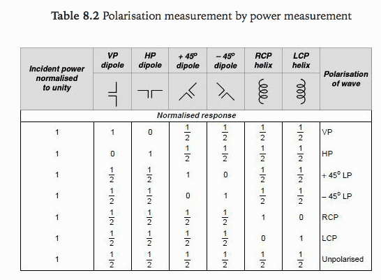
where,
VP = vertical polarization
HP = horizontal polarization
LP = linear polarization
RCP = right circular polarization
LCP = left circular polarization
References: Antenna and Wave Propagation by G.S.N. Raju