Block Diagrams:
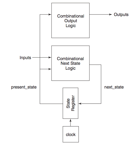
From Figure 1, we can see that in Moore’s FSM,
- Input goes into the combinational next state logic block whose outputs are fed to state register.
- The outputs of the state register are fed to combinational output logic block which gives us the outputs.
- Also, the output of state register is also feedback to the combinational next state logic. Therefore, outputs of Moore FSM depends only on the present state.
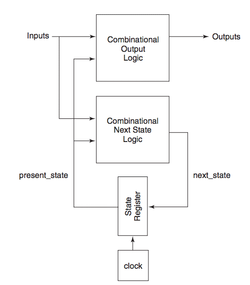
From Figure 2, we can see that in Mealy’s FSM,
- Apart from the present state, present input also affects its outputs.
- The basic structure is same for Mealy and Moore FSM.
State Diagrams:
A state diagram provides an abstract graphical representation of the operation of an FSM. It allows the conceptualization of the FSM’s operation to be separated from its implementation. Each individual state of the FSM is represented by a state circle, with the state’s name located inside.
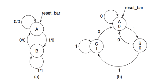
Mealy FSM state diagram has two states, A and B. A state diagram for a Mealy FSM has each directed arc labelled with an input/output value pair. This value pair indicates the FSM’s output when it is in the state from which the arc emanates and has the specified input value. This clearly indicates that the FSM’s outputs are a function of its inputs and present state.
It means that transition from A to B has an input of 1 and output of 0. Similarly, the transition from B to A has an input of 0 and output 0.
In Moore’s FSM state diagram, each directed arc is labelled with the input values that cause the transition to the next state. Output values are associated with the state circles rather than the directed arcs. These output values are usually written inside the state circle below the state name.