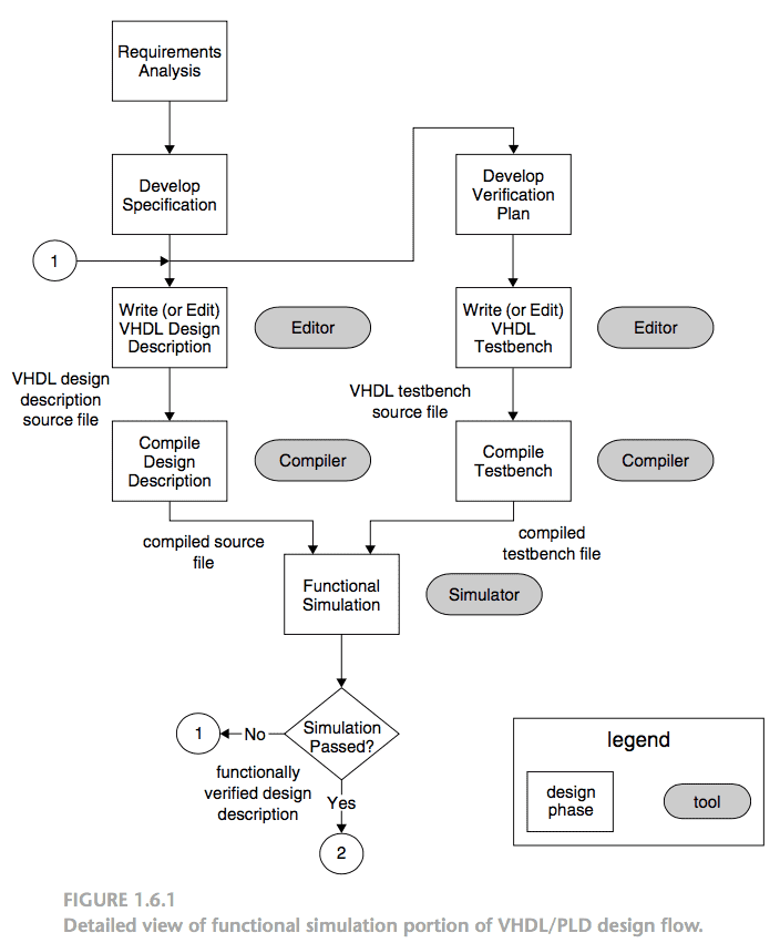
1. A functional simulation simulates the design description to verify its logical correctness. A circuit represented in the form of logic expressions can be simulated to verify that it will function as expected. The tool that performs this task is called a functional simulator.
2. Functional simulation is necessary for complex designs, because early detection of logical errors saves significant time and expense.
3. It uses the logic expressions (often referred to as equations) generated during synthesis, and assumes that these expressions will be implemented with perfect gates through which signals propagate instantaneously.
4. The simulator requires the user to specify values for the circuit’s inputs that should be applied during simulation. For each input value, the simulator evaluates the outputs produced by the expressions.
5. The results of simulation are usually provided in the form of a timing diagram which the user can examine to verify that the circuit operates as required.
6. In functional simulation, the waveforms do not show any delay from an input change to a corresponding output change. That is, as soon as a UUT (under unit test) input changes, its outputs respond instantaneously.
7. During Functional simulation, logically debugging of design description is done and dynamic semantic errors are detected. Since the design description is the UUT, changes in signal values during the functional simulation map directly to statements in our source code.
Reference: VHDL for Engineers by Kenneth L. Short