Verification using Simulation:
1. Verification is the process used to demonstrate the correctness of a design. We verify that our design description meets its functional and timing specifications before the target PLD is programmed.
2. Verification using simulation can show the existence of errors in a design, but cannot prove that a design is correct.
3. The simulator allows input values to be applied to the design description. In response, the simulator computes the corresponding output values by executing statements in the design description.
4. When errors are encountered during a simulation, we can use the simulator’s debugging features to find and correct the source of the errors in the design description. Once modified, a design description must be compiled and simulated again to verify that the errors have indeed been corrected.
5. Simulation is performed during three different phases of the design flow:
- Functional simulation: we simulate our VHDL design description. This simulation is performed to verify that the system we described meets the functional requirements of its specification.
- Post-synthesis (gate-level) simulation: we simulate the synthesized VHDL netlist. This netlist is a gate-level VHDL model of the synthesized logic. It is automatically generated by the synthesizer. This simulation is performed to verify that the synthesized logic is functionally correct.
- Timing (post-route) simulation: we simulate the VHDL timing model of the synthesized logic mapped to the target PLD. The VHDL timing model is automatically generated by the place-and-route tool. This simulation is performed to verify that the synthesized logic, as mapped to the target PLD, meets all timing constraints.
6. A simulator requires a sequence of input values (stimulus) to apply to the VHDL model being verified. If an appropriate sequence of input values is created, it can be used for all three kinds of simulation. There are three approaches to generating stimulus: interactive (manual), command line, and testbench.
- An interactive simulator allows us to manually apply a stimulus.
- Commands in the stimulus language allow us to specify input waveforms. These commands can be entered interactively or placed in a file and executed.
Testbench:
1. A testbench is a VHDL program that applies a predetermined stimulus to a design entity during simulation.
2. A testbench can be written to also verify the output values produced by the design entity. If there is a difference between the expected and the actual output values, the testbench generates an error message.
3. A testbench is basically a stimulus-response system.
4. The design entity being verified is usually called the unit under test (UUT).
5. Strictly speaking, testing refers to the process of determining whether a design was manufactured correctly. In contrast, verification is performed to determine whether a design meets its specifications before it is manufactured in quantity.
6. Testbench consists of a testbench entity declaration and its associated architecture body. A simple testbench architecture body contains:
• An instance of the UUT
• Signals mapped to the UUT’s ports
• A process statement that applies stimulus to the UUT, via the signals
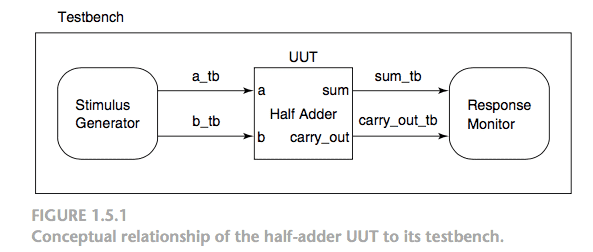
A testbench completely encloses its UUT and simulates the environment in which the design will operate.
7. A testbench is entirely self-contained i.e. it has no inputs or outputs.
8. Statements in the testbench’s architecture body apply stimulus values to signals that connect to the UUT’s inputs. Other statements monitor the output values from the UUT.
- For a functional simulation, our VHDL design description is the UUT.
- For a post-synthesis simulation, the VHDL netlist model (the synthesized gate-level logic) is the UUT.
- For a timing simulation, the VHDL timing model (produced by the place-and-route tool) is the UUT.
9. The relationship between the half-adder UUT and its testbench is illustrated.
Reference: VHDL for Engineers by Kenneth L. Short