1. It is a radiating element which has the shape of a horn. It is a waveguide, one end of which is flared out.
2. A waveguide, when excited at one end and open at the second end, radiates.
3. However, radiation is poor and non-directive pattern results because of the mismatch between the waveguide and free space. The mouth of the waveguide is flared out to improve the radiation efficiency, directive pattern and directivity.
Types of Horn:
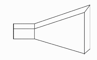
- Sectoral horn: It is a horn in which flaring exists only in one direction.
- It is of two types:
- Sectoral H-plane horn – if flaring is along direction of magnetic field H
- Sectoral E-plane horn – if flaring is along the direction of electric field E
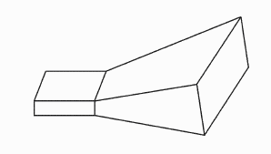
- Pyramidal (Rectangular) horn: It is a horn in which flaring is along both E and H. It has a shape of a truncated pyramid.
- Conical horn: If walls of a circular waveguide are flared out, a conical horn is obtained.
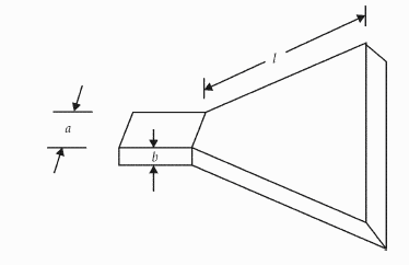
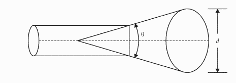
Horn Parameters:
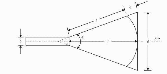
δ = path difference
l = axial length
d = aperture dimension
θ = flare angle
Operation:
1. In a waveguide, propagation is restricted by the conducting walls and waves will not spread.
2. After reaching the mouth, waves spread laterally and wavefront becomes spherical.
3. At the mouth of the waveguide, there exists a near-field region where the wavefront is a complicated one. This is considered to be the transition region where a change of propagation from the waveguide to free space takes place.
4. As the waveguide impedance and free space impedance do no match, the mouth of the waveguide is flared out.
5. This flaring provides impedance matching and improves the radiation efficiency, directive pattern and directivity.
Design Equations for Horn Antenna:


Where,
δ = path difference
l = axial length
d = aperture dimension
θ = flare angle
(arctan means inverse of tan)
(arccos means inverse of cos)
Half-power beam width:


Where,
ϕE = HPBW in E-plane
ϕH = HPBW in H-plane
dE = aperture in E-plane in free space wavelength
dH = aperture in H-plane in free space wavelength
Directivity of Horn Antenna:

Power Gain:

Where,
For Rectangular Horn:
Aa = dEdH = physical area of the aperture.
For Conical Horn:
Aa = πd
where d = aperture diameter
Applications of Horn Antenna:
1. Horns are used at microwave frequencies where moderate gains are sufficient.
2. They are used as feed elements.
3. They are often used in laboratories for the measurement of different antenna parameters.