The serial adder is a digital circuit in which bits are added a pair at a time.
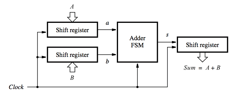
Let A and B be two unsigned numbers to be added to produce Sum = A + B. In this we are using three shift registers which are used to hold A, B and Sum. Now in each clock cycle, a pair of bits is added by the adder FSM and at the end of the cycle, the resulting sum is shifted into the Sum register.
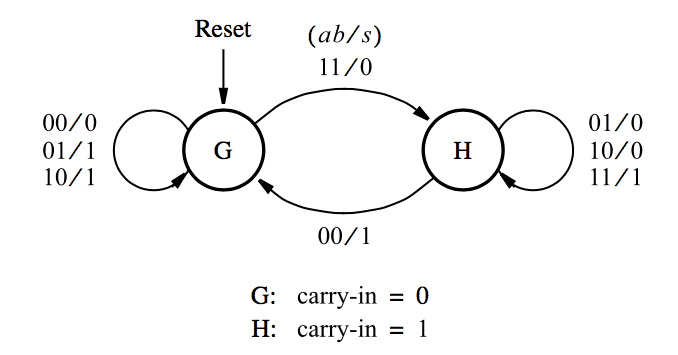
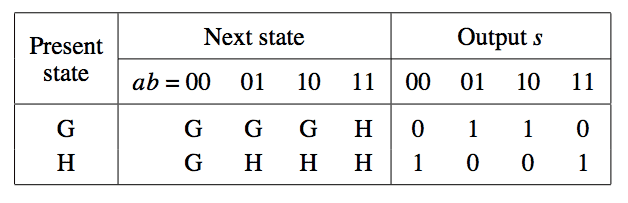
Mealy type FSM for serial adder:
Let G and H denote the states where the carry-in-values are 0 and 1. Output value s depends on both the state and the present value of inputs a and b.
In state G and H:
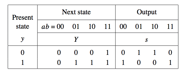
A single Flip-Flop is needed to represent the two states. The next state and output equations are:
Y = ab + ay + by
s = a ⊕ b ⊕ y
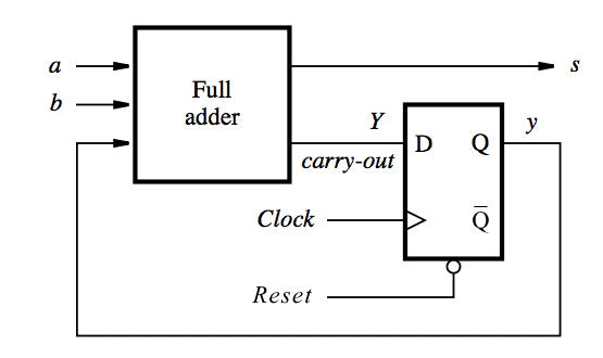
The flip-flop can be cleared by the Reset signal at the start of the addition operation.
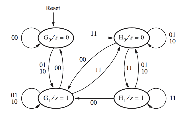
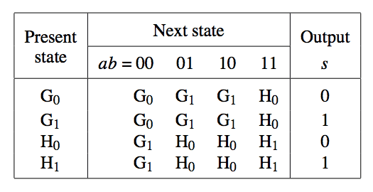
Moore type FSM for serial adder:
In a Moore type FSM, output depends only on the present state. Since in both states, G and H, it is possible to produce two different outputs depending on the valuations of the inputs a and b, a Moore type FSM will need more than two states. Therefore we will four states namely: G0, G1, H0 and H1.
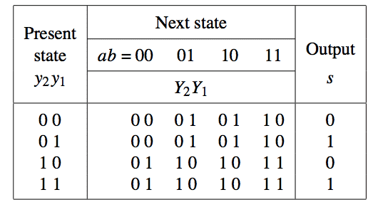
The next state and output equations are:
Y1 = a ⊕ b ⊕ y2
Y2 = ab + by2 + by2
s = y1
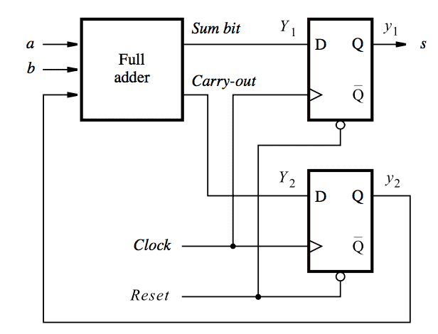
The only difference between circuits of Mealy and Moore type FSM for serial adder is that in Moore type FSM circuit, output signal s is passed through an extra flip-flop and thus delayed by one clock cycle with respect to the Mealy type FSM circuit.
References: Fundamentals of Digital Logic with VHDL Design
Good blog post. I certainly appreciate this website.
Thanks!
How did you make your diagrams?
You can make these type of diagrams using a website – http://www.draw.io
how about the verilogcode ?
This is how world works kiddo!!
Can you give the coding based on the block diagram at above .?
what about the input like A: 10101 B: 10010 in this case where we will find the last carry generated by 1 1 addition
Great article, thank you!
where is the code?
Please share asm also